

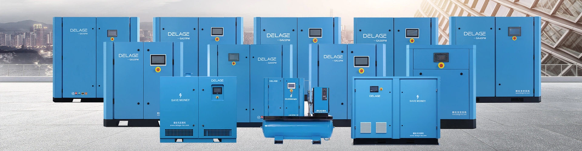

The rotary centrifugal compressor uses an impeller to drive the gas to rotate at high speed, causing the gas to generate centrifugal force. Due to the expansion flow of the gas in the impeller, the flow rate and pressure of the gas after passing through the impeller are increased, and compressed air is continuously produced.
Rotary centrifugal compressors are speed compressors. When the air load is stable, the centrifugal air compressor works stably and reliably.
① Compact structure, light weight, wide exhaust range;
② Few wearing parts, reliable operation and long life;
③The exhaust is not contaminated by lubricating oil and the air supply quality is high;
④The efficiency is high when the displacement is large, and it is conducive to energy saving.
The rotary centrifugal compressor is mainly composed of two parts: the rotor and the stator. The rotor includes an impeller and a shaft. There are blades on the impeller, as well as a balance plate and part of the shaft seal. The main body of the stator is the casing (cylinder), and the stator is also equipped with a diffuser, a bend, a return flow device, an air inlet pipe, an exhaust pipe and some shaft seals. The working principle of the centrifugal compressor is that when the impeller rotates at high speed, the gas rotates with it. Under the action of centrifugal force, the gas is thrown into the diffuser behind, and a vacuum zone is formed at the impeller. At this time, the fresh gas from the outside is Enter the impeller. The impeller rotates continuously, and the gas is continuously sucked in and thrown out, thereby maintaining a continuous flow of gas.
Rotary centrifugal compressors rely on changes in kinetic energy to increase gas pressure. When the rotor with blades (i.e., the working wheel) rotates, the blades drive the gas to rotate, transferring work to the gas, so that the gas obtains kinetic energy. After entering the stator part, due to the expansion effect of the stator, the speed energy pressure head is converted into the required pressure. The speed decreases and the pressure increases. At the same time, the guiding effect of the stator part is used to enter the next stage impeller to continue to increase the pressure, and is finally discharged from the volute. . For each compressor, in order to achieve the design required pressure, each compressor is equipped with a different number of stages and stages, and even consists of several cylinders.
The air system of the rotary centrifugal compressor is not complicated. The outdoor air is connected to the air inlet of the air compressor through the suction tower and the air filter. The high-speed rotating impeller inside the air compressor does work on the air, changing the air pressure and temperature. , the flow rate increases, and then flows into the diffuser, and then the air flow rate decreases, the pressure further increases, and the air flows into the next stage impeller through the guide device to continue compression. Since the temperature of the air continues to rise after being compressed step by step, compressing air with high temperature in the next stage requires more power. In order to lower the air temperature and reduce compression power consumption, in the air system of the multi-stage centrifugal air compressor , the structure of segmented intermediate cooling is often used. Therefore, in this project, the air is compressed to 0.241MPa and 151℃ in one stage (a stage can include several stages or only one stage), and is discharged from the air compressor body through the exhaust port of one stage, and an intercooler and circulation are introduced. The water undergoes a heat exchange, and the cooled compressed air is connected to the second-stage air inlet of the air compressor and continues to be compressed to 0.379MPa and 99°C. It is discharged from the air compressor body through the second-stage exhaust port and introduced into the final cooler and circulation The water undergoes secondary heat exchange, and the cooled compressed air is dried by the air heater and then transported to various air consumption points through pipelines.
Rotary centrifugal compressor parameter table
|
(Model) |
Exhaust pressure |
exhaust volume |
power |
Dimensions(mm) |
net weight |
|
|
barg |
(m3/min) |
KW |
HP |
Size(LXWXH) |
(kg) |
|
|
ZH300 |
0.6-9 |
24-48 |
132-263 |
176-350 |
2750*1550*1820 |
3800 |
|
ZH450 |
0.6-9 |
36-61 |
200-335 |
300-450 |
3150*1800*1850 |
4500 |
|
ZH600 |
0.6-1.2 |
56-83 |
300-450 |
400-600 |
3280*1850*2200 |
6300 |
|
ZH900 |
0.6-1.2 |
76-122 |
400-640 |
530-900 |
3800*2000*2250 |
8160 |
|
ZH1200 |
0.6-1.2 |
118-150 |
630-800 |
840-1200 |
4200*2150*2350 |
11500 |
|
ZH1500 |
0.6-1.6 |
142-215 |
760-1120 |
1010-1750 |
4200*2150*2350 |
12000 |
|
ZH2000 |
0.6-1.6 |
186-310 |
980-1600 |
1320-2150 |
4600*2200*2500 |
17200 |
|
ZH3000 |
0.6-1.6 |
268-438 |
1380-2250 |
1840-3000 |
5300*2300*2970 |
21500 |
|
ZH4000 |
0.6-2.5 |
347-550 |
1800-2850 |
2400-3800 |
600*4500*3500 |
40000 |
|
ZH6500 |
0.6-2.5 |
530-920 |
2660-4540 |
3550-6090 |
8500*4200*4200 |
45000 |
Hot Tags: rotary centrifugal compressor, China rotary centrifugal compressor manufacturers, suppliers, factory


